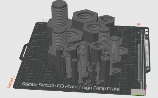
Reliable printed threads start with the right geometry and clearance. Learn how to model, orient, slice and test threaded parts, from screw-top containers to nuts and bolts.
1. Start with a customizable design
Getting two printed threads to turn smoothly together takes more than matching nominal dimensions. Layer resolution, material behavior and extrusion settings all affect fit.
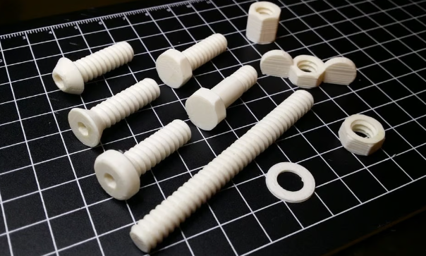
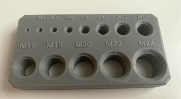
A parametric generator can save time when you need a threaded container or a simple fastener. The supplied guide highlights MakerWorld projects by 3Dkastle for M3–M24 bolts, nuts and washers, Gentle Design for screw-top containers, and Maochen for eye bolts. Check the selected model’s dimensions, license and handedness before use. A familiar starting model still needs a fit test on your printer.
2. Understand the thread you are printing
A screw is a component; its thread is a helical feature. External threads project from a shaft or container neck, while internal threads run inside a nut or lid. Their pitch, profile and handedness must match. Triangular profiles are common in fastening. Trapezoidal profiles are used in motion systems, and rounded or modified profiles can suit repeatedly opened containers. Layer-by-layer printing approximates the helix with small steps, so geometry and orientation affect both surface quality and fit.
3. Learn the key dimensions
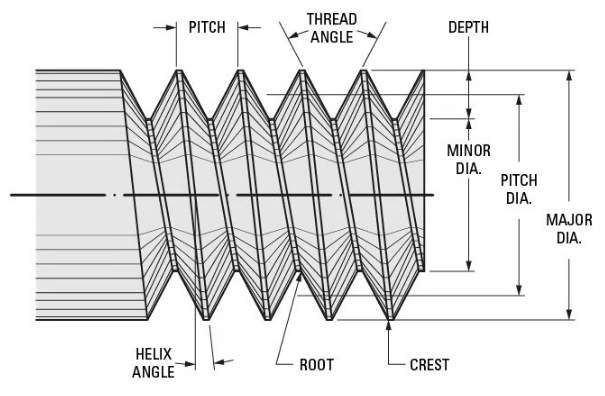
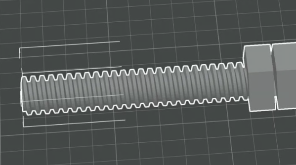
The thread axis runs through the center of the part. The crest is the top of a thread and the root is the bottom of its groove. Major diameter is measured across external crests or internal roots; minor diameter is measured across external roots or internal crests. Pitch is the axial distance between corresponding points on adjacent threads. Right-hand threads tighten clockwise when viewed from the turning end; left-hand threads tighten counterclockwise. A left-hand nut cannot mate correctly with a right-hand bolt. For multi-start designs, distinguish pitch from lead, the distance traveled in one full revolution.
4. Set a practical starting specification
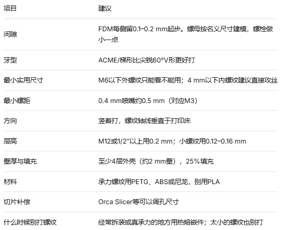
For a custom FDM thread, the supplied guide suggests starting with approximately 0.1–0.2 mm of radial clearance per side, an upright thread axis and a relatively coarse profile. These are trial values, not universal settings. Nozzle size, material, geometry and loading may require different choices. Choose wall count and infill for the load path. Do not assume a particular number of perimeters produces a fixed wall thickness: actual thickness depends on extrusion width. Printed fasteners also need to be evaluated for layer separation, creep and repeated use.
5. Match the standard when using commercial hardware
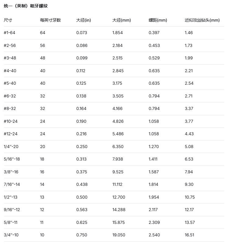
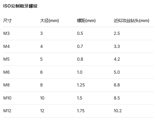
If a printed part must accept a commercial screw or nut, match the relevant thread standard, pitch and handedness. A custom container can use a purpose-designed profile, provided both mating components agree. In metric designations, M5 specifies a nominal major diameter of 5 mm; it does not alone identify every possible pitch. Unified inch threads use diameter or gauge size together with threads per inch. Use a verified thread table for the exact designation. The approximate tap-drill rule of major diameter minus pitch is a starting estimate, not a replacement for the appropriate tooling table. Metric coarse size Pitch (mm) Typical tap drill (mm) M3 0.5 2.5 M4 0.7 3.3 M5 0.8 4.2 M6 1.0 5.0 M8 1.25 6.8 M10 1.5 8.5 M12 1.75 10.2
6. Build in clearance
Printed holes can come out undersized, while extrusion and shrinkage can change the effective thread dimensions. Two nominally matching surfaces may therefore bind. Offset the mating geometry or use a suitable slicer compensation setting. For custom FDM parts, try a small series around 0.1–0.2 mm radial clearance per side. A radial change of 0.1 mm corresponds to a 0.2 mm diameter change. Keep that distinction clear when comparing CAD offsets with slicer settings. Print the test in the same material and orientation as the final part.
7. Choose a printable profile
A sharp 60-degree triangular thread creates challenging overhangs. A coarser trapezoidal or rounded profile can be easier to print for a custom lid or mating pair. Keep the specified profile when interfacing with standard metal hardware. Add a lead-in chamfer to help the parts align without cross-threading. A 45-degree chamfer is a useful starting geometry, but its size should suit the thread and available wall thickness.
8. Test small threads before committing
Fine features become harder to reproduce as their size approaches the printer’s extrusion width and layer height. With a 0.4 mm nozzle, small functional threads can be demanding; M6 is a practical point for caution, not a hard capability limit. Print a short bolt-and-nut pair or a section of the intended joint. Assess starting engagement, running friction, looseness and the actual working load. Metal fasteners, captive nuts or inserts may be more suitable for demanding or repeatedly serviced connections.
9. Design screw-top containers as a matched pair
Give the neck and lid matching pitch and profiles, then add sufficient clearance. Coarse threads and forgiving crests can improve printing and repeated opening. Add a lead-in and leave enough surrounding material to support the thread. Print a short neck segment and lid first. An upright thread axis often improves the surface, while a lid printed with its flat exterior top on the bed may reduce support requirements. Check the actual geometry before choosing the orientation. A threaded closure alone does not guarantee an airtight or watertight seal; a gasket or O-ring may be needed.
10. Export real thread geometry
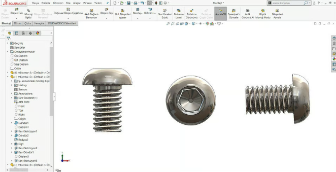
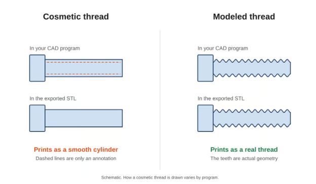
CAD systems may display cosmetic threads that are only visual annotations. Printable threads must exist as modeled geometry in the exported mesh. Inspect the STL or 3MF in the slicer to confirm that the helical features are present, rather than assuming the shaded CAD view proves it.
11. Use component libraries carefully
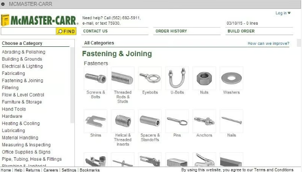
Hardware libraries can provide useful dimensions and starting geometry. In Fusion, the McMaster-Carr component workflow can bring commercial hardware models into an assembly. Such models may be intended for design reference rather than printing, so check for actual thread geometry and add the fit allowance your process needs.
12. Model internal and external threads in Fusion
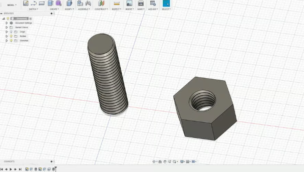
For an external thread, create a cylindrical shaft, select its cylindrical face in the Thread tool, choose the required specification and enable Modeled . Add the fastener head and lead-in features as needed. For an internal thread, create the surrounding body and a suitable cylindrical hole, then apply the matching thread specification to the inner face with Modeled enabled. Inspect the generated hole and thread dimensions. A standard thread class does not eliminate the need to tune clearance for your printer.
13. Apply the same geometry checks in other software
Onshape, FreeCAD and Blender offer different routes to thread geometry, including dedicated tools, community features and add-ons. Feature availability depends on the software version and extension. In every case, verify that the thread is an actual solid or mesh feature, set the intended pitch and add clearance deliberately. Before export, check for invalid or non-manifold geometry. Reopen the exported mesh in the slicer and inspect several layers through both the external and internal thread.
14. Select material for the application
Material choice affects wear, stiffness, temperature resistance, creep and layer bonding. PETG, ABS and nylon can be useful candidates, but none is automatically suitable for every threaded connection. PLA may work for prototypes and light-duty uses; avoid treating material names alone as proof of load capacity. Calibrate extrusion flow and the first layer. Excess material can tighten the fit, while under-extrusion can weaken the thread. Orientation also matters: an upright bolt may print cleanly but remain vulnerable to tensile separation between layers.
15. Tune the slicer for the thread
An upright thread axis is a useful starting point for clean geometry and reduced support. Keep support away from mating surfaces where possible, since removal can damage the flanks. Compare another orientation when the required load direction makes layer adhesion a concern. The supplied guide suggests 0.2 mm layers for larger threads and 0.12–0.16 mm for smaller ones. Treat those as test settings. Choose wall thickness and infill for the part, not a fixed recipe. Cooling can improve overhang definition, but excessive cooling may compromise bonding with some materials. Check the filament maker’s guidance.
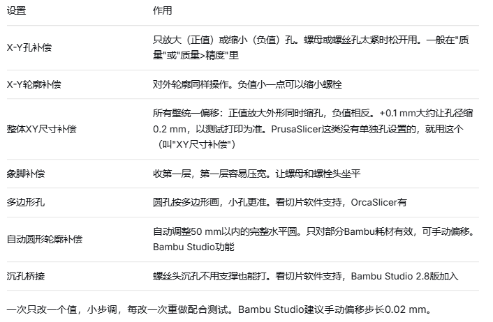
16. Use compensation and diagnose the result
Hole-specific compensation can adjust internal openings without changing the entire outside profile. Contour compensation can adjust the external boundary. Global XY compensation affects both, so check its sign and behavior in your slicer’s current documentation and preview. Elephant-foot compensation can help when the first layer flares outward and blocks engagement. Change one setting at a time in small steps and print another mating test. Do not assume identically named settings behave the same across slicers. Problem What to check The nut will not start Pitch and handedness, clearance, flow, lead-in and debris. The fit is too loose Excess clearance or compensation; reduce the adjustment and retest. The thread breaks under load Material, wall thickness, layer orientation and whether metal hardware is needed. The surface is rough Layer height, cooling, overhangs and extrusion calibration. Very small threads will not resolve Use a larger thread or consider tapping a suitable pilot hole. Technical reference: Autodesk Fusion documentation on modeled threads .